ENG-01Engineering · Cooling
Direct-to-chip liquid cooling, explained
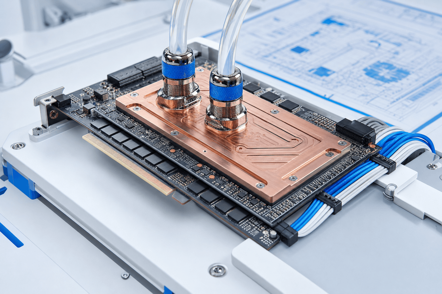
Coolant runs through cold plates mounted on the processors, so heat leaves the silicon through liquid instead of room air. A coolant distribution unit then hands that heat to a facility loop for rejection or reuse.
- 2
- Loops, one heat exchanger
- 6
- Stages, plate to rejection
- 0
- Water used by a closed loop
What you need to know
Air ran out of headroom
Industry-average PUE has been essentially flat for about six years while rack densities climbed into the 10–30 kW band.
It is two loops, not one
A treated technology loop touches the IT; a facility loop carries heat away. A plate heat exchanger keeps them separate.
Temperature is the real prize
Warm supply water unlocks dry-cooler free cooling and makes recovered heat useful to an adjacent process.
It never removes all the heat
Regulators, drives, and power supplies still need an air path. Every design runs two cooling systems.
The system, end to end
Two loops joined by a heat exchanger
The Open Compute Project maintains vendor-neutral requirements for the parts — cold plates, CDUs, quick disconnects — so hardware from different vendors can share one loop.
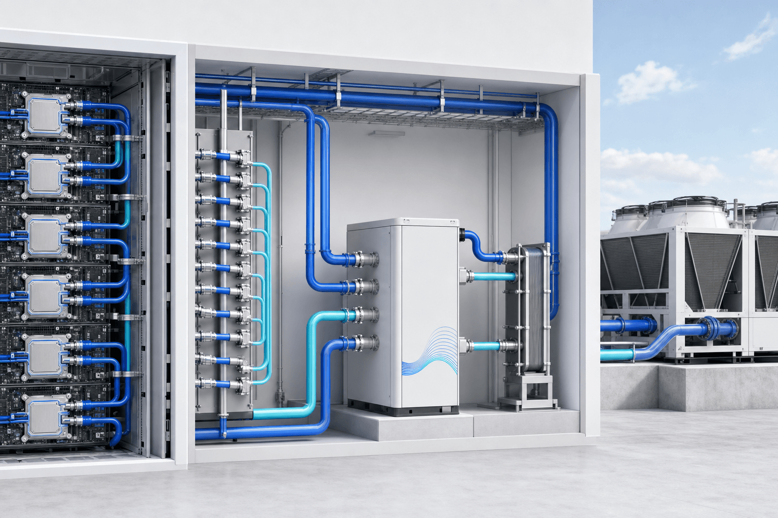
Cold plate
Microchannel plate on the die package. Absorbs heat by conduction into the coolant.
Manifold + QD
Distributes coolant across the rack. Dripless couplings let a server be pulled without draining.
CDU
Pumps, filters, controls temperature, and isolates the technology loop from facility water.
Rejection
Dry coolers, evaporative towers, or a heat-reuse exchanger feeding another process.
Why the industry moved
Air is a poor coolant, and the hardware stopped waiting
Air has carried data-center heat for decades because it is free and simple, but it is a poor coolant: low density, low heat capacity, and it needs large temperature differences and high fan power to move meaningful energy. ASHRAE's TC 9.9 — the committee that defines the thermal envelopes IT vendors design to — published a dedicated white paper on why liquid cooling is expanding into mainstream facilities as rack densities climb beyond what airflow can economically serve.[2] Its thermal guidelines now define liquid-cooling facility water classes alongside the familiar A1–A4 air classes.[1]
AI hardware forces the issue. NVIDIA's GB200 NVL72 packs 72 GPUs and 36 CPUs into one liquid-cooled rack acting as a single NVLink domain — the vendor ships it liquid-cooled because an air-cooled version of that density is not on offer.[7]Meanwhile the Uptime Institute's 2025 survey of 800+ operators shows fleet-wide rack densities rising into the 10–30 kW band and industry-average PUE essentially flat for about six years — evidence that incremental air-side tuning has run out of headroom.[6] Google's fleet-wide trailing-twelve-month PUE of 1.09 (per its latest reporting) marks the practical ceiling of what world-class air-and-water plants achieve at scale.[9]
LC-02 · Manifold, quick disconnects, and flow instrumentation
Component by component
What each stage actually does
The order an engineering review walks the loop, and the thing that fails first at each stage.
- LC-01
Cold plate
A machined microchannel plate is clamped to the GPU or CPU package over a thermal interface material, and coolant absorbs the heat conducted out of the die. Mounting pressure and interface degradation are what quietly cost you performance.
- LC-02
Manifolds and quick disconnects
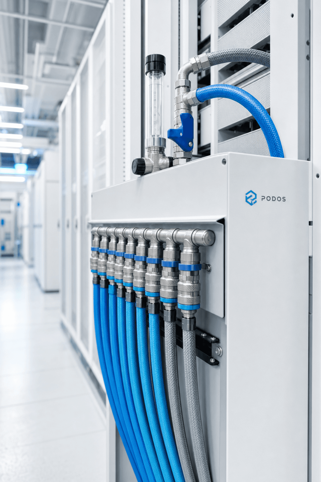
Coolant is distributed across the servers in a rack. Dripless couplings let a technician pull a server without draining the loop — and OCP conformance is what keeps those couplings interchangeable across vendors.
- LC-03
Coolant distribution unit
Pumps, filtration, controls, and a plate heat exchanger that isolates the technology loop from facility water. It also holds supply temperature above dew point, which is the difference between cooling a rack and condensing water on it.
- LC-04
Technology loop
The treated-coolant circuit between CDU and cold plates. Chemistry and wetted-material compatibility are monitored for the life of the system; a neglected loop degrades silently.
- LC-05
Facility water loop
Carries rejected heat from the CDUs to the rejection plant. Its supply temperature is what defines the ASHRAE facility water class the design sits in.
- LC-06
Heat rejection or reuse
Dry coolers, evaporative towers, chillers, or an exchanger handing the heat to an adjacent process. This is the stage — not the cooling method — that decides site water consumption.
Reference
The loop as a bill of materials
Six stages, what each one is for, and the item that decides whether it survives five years in operation.
| Stage | Component | Function | Primary failure / watch item |
|---|---|---|---|
| LC-01 | Cold plate | Microchannel plate clamped to the GPU or CPU package over a thermal interface material; coolant absorbs heat conducted from the die. | Mounting pressure, interface-material degradation, channel fouling. |
| LC-02 | Manifolds + quick disconnects | Distribute coolant across servers in a rack; dripless quick disconnects allow a server to be pulled without draining the loop. | Seal wear; interoperability between vendors.[4] |
| LC-03 | CDU | Pumps, filtration, controls, and a plate heat exchanger isolating the technology loop from facility water. Built at in-rack, in-row, or facility scale. | Pump redundancy; control of coolant supply temperature above dew point. |
| LC-04 | Technology loop | The treated-coolant circuit between CDU and cold plates, with monitored chemistry and wetted-material compatibility. | Corrosion and biological growth control. |
| LC-05 | Facility water loop | Carries rejected heat from CDUs to the heat-rejection plant; its supply temperature defines the ASHRAE facility water class.[1] | Flow balancing across many CDUs. |
| LC-06 | Heat rejection / reuse | Dry coolers, evaporative towers, chillers, or a heat-reuse exchanger feeding another process. | Water consumption vs approach temperature tradeoff. |
Coolant classes
Single-phase is the default; two-phase buys flux
Two coolant families dominate direct-to-chip designs. Single-phase water-based coolants — treated water or propylene-glycol mixes — stay liquid through the loop and win on heat capacity, cost, and mature chemistry; OCP's cold-plate requirements document the wetted-material and quality expectations that keep them stable.[4]
Two-phase dielectric fluids boil inside the cold plate, absorbing heat as latent energy. They capture very high heat flux and are non-conductive at the chip, but bring pressure management, higher fluid cost, and growing regulatory scrutiny of engineered fluorocarbons. OCP's accelerator-infrastructure guidelines cover liquid-cooling practice for exactly the multi-GPU systems driving these choices.[5]
Warm water and free cooling
The quiet advantage is temperature
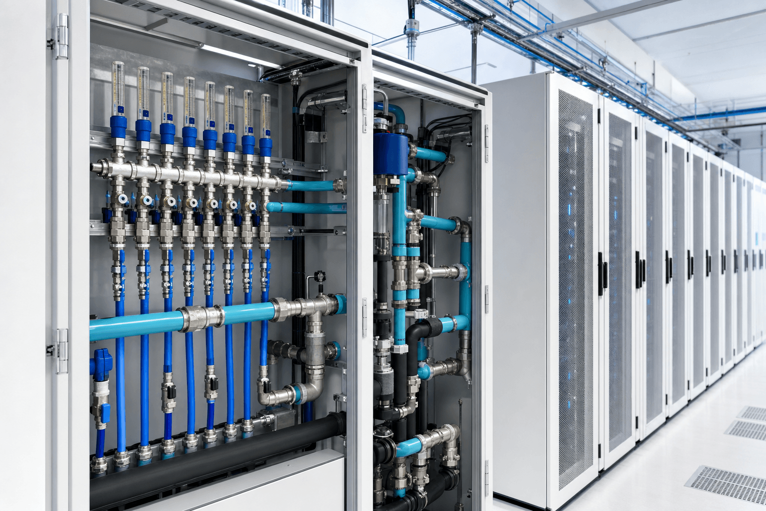
Because liquid pulls heat straight off the die, the loop can run far warmer than the chilled air an air-cooled room needs. ASHRAE names facility water classes by their maximum supply temperature, and the warmer classes matter economically: if the IT accepts warm supply water, heat can be rejected through dry coolers for most or all of the year — free cooling — instead of through compressor-driven chillers.[1]
Warm return water is also what makes heat reuse practical: the higher the return temperature, the more useful the heat is to an adjacent process. Federal-lab guidance treats warm-water direct-to-chip loops as the enabling step for both free cooling and energy recovery.[8]The rejection choice then sets the site's water story — evaporative towers consume water to reach lower temperatures; dry coolers consume none but need warmer loops or more surface area.
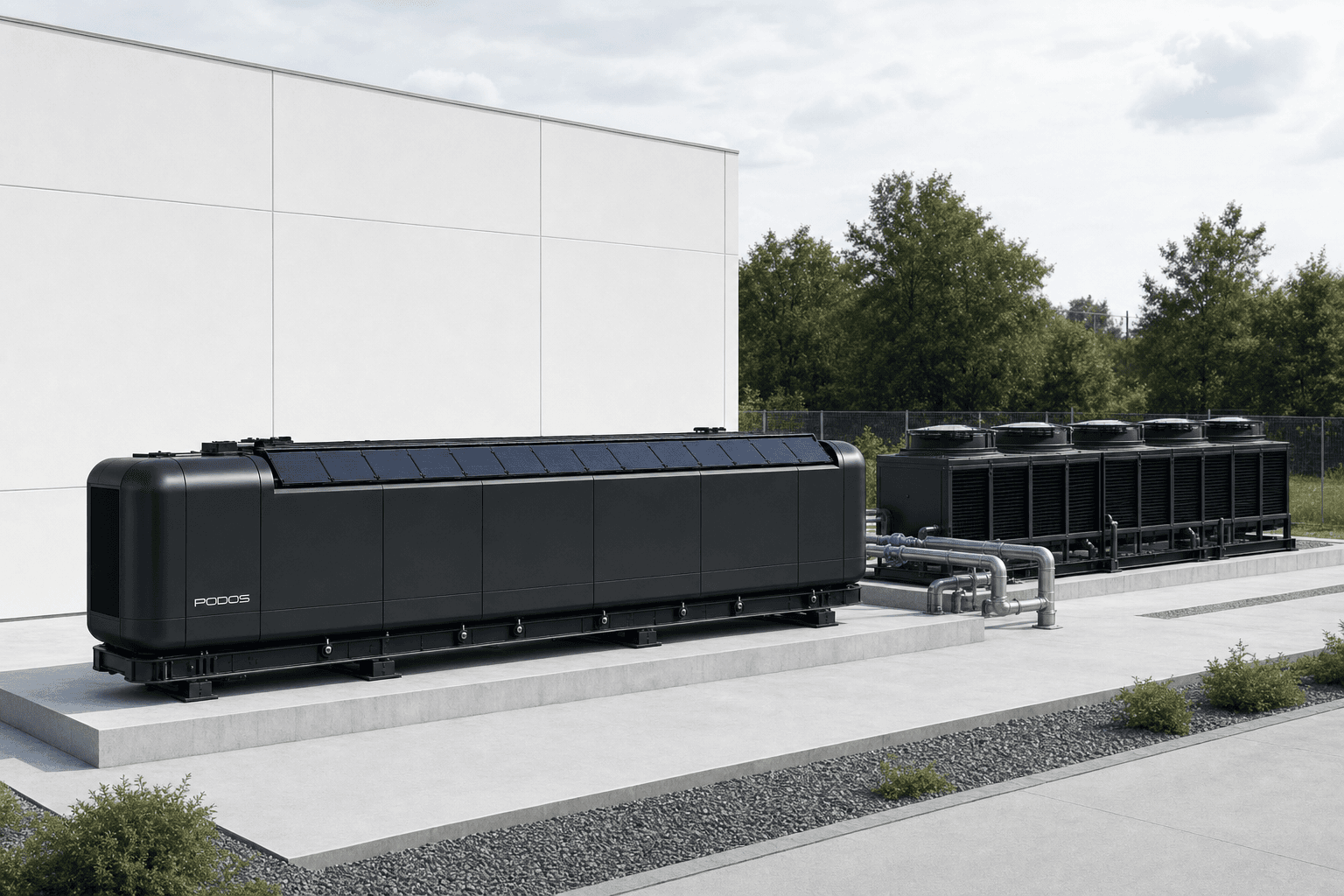
A closed technology loop paired with dry-cooler rejection consumes no water in operation — which makes water a siting decision, not a property of liquid cooling.
0
Litres consumed by the loop itself
Selecting a configuration
The eight questions that decide the design
In roughly the order an engineering review asks them.
| # | Criterion | What to evaluate | Design consequence |
|---|---|---|---|
| 01 | Rack density trajectory | Sustained kW per rack over the hardware refresh horizon, not the day-one figure. | Densities beyond the economic reach of air push the design to liquid; survey data shows the fleet already moving into the 10–30 kW band.[6] |
| 02 | Facility water class | The warmest ASHRAE facility water class the selected IT hardware accepts. | Warmer classes unlock dry-cooler free cooling and reduce or eliminate chiller plant.[1] |
| 03 | Heat-rejection path | Local water availability, permits, climate, and approach temperatures. | Evaporative towers trade water for temperature; dry coolers trade temperature for zero water. |
| 04 | Coolant class | Single-phase water/glycol vs two-phase dielectric; serviceability vs heat-flux ceiling. | Single-phase is the mainstream default; two-phase suits extreme flux with added pressure management.[5] |
| 05 | Residual air fraction | How much server heat the cold plates cannot capture (VRs, drives, PSUs, NICs). | Sizes the remaining air-cooling plant; no direct-to-chip design eliminates it.[8] |
| 06 | CDU placement | In-rack, in-row, or facility-scale CDUs against floor loading and pipe routing. | In-rack/in-row suits retrofits and small footprints; facility CDUs suit new builds at scale.[3] |
| 07 | Interoperability | Conformance with OCP cold-plate and quick-disconnect requirements. | Keeps the loop open to multiple server vendors across refresh cycles.[4] |
| 08 | Heat-reuse ambition | Whether an adjacent heat consumer exists and what return temperature it needs. | Favors warm-water loops and placing the heat exchanger where a consumer can connect.[8] |
HONEST LIMITS
Operational tradeoffs and honest limitations
Direct-to-chip cooling is not a free upgrade, and designs that pretend otherwise fail in operation.
- It does not capture everything. Cold plates cool the components they touch; the residual heat load from regulators, drives, and power supplies still requires an air path, so the facility runs two cooling systems, not one.
- Coolant is now an operations discipline. Chemistry, filtration, and wetted-material compatibility must be monitored for the life of the loop; a neglected technology loop degrades quietly until it damages hardware.
- Leaks are low-probability, high-consequence. Dripless disconnects, leak detection, and rehearsed isolation procedures are mandatory engineering, not options.
- Service procedures change. Technicians disconnect fluid couplings rather than sliding servers out of airflow, and commissioning adds pressure testing and flow balancing that air-cooled rooms never needed.
- Standards are still maturing. OCP requirements reduce vendor lock-in but do not yet guarantee that every cold plate, coupling, and CDU interoperates across generations.
In the product
How the PODOS Pod applies direct-to-chip cooling
PODOS builds these choices into a factory-integrated unit rather than a field-built plant. Each PODOS Pod is designed as a standardized 1 MW building block, designed for 128 GPUs, with closed-loop direct-to-chip liquid cooling specified as part of the enclosure rather than added to a room. Because the cold plates, manifolds, CDU, and heat-rejection interfaces are integrated and tested in the factory, the cooling system ships as a commissioned subsystem — one reason PODOS targets a 90-day window from order to commissioning for a standard unit.
The same closed-loop architecture shapes the rest of the system: the power architecture that feeds the racks, the deployment model that treats cooling as cargo instead of construction, and the broader modular platform those units compose into.
QUESTIONS
Frequently asked questions
Does direct-to-chip cooling remove all of a server's heat?
No. Cold plates capture heat only from the components they touch — typically GPUs, CPUs, and sometimes memory. Heat from voltage regulators, drives, NICs, and power supplies still leaves through air, so every direct-to-chip design keeps a smaller air-cooling path sized for that remainder.
Does a closed-loop liquid cooling system consume water?
The loop itself does not — the same coolant circulates continuously. Site water consumption is decided by the heat-rejection stage: evaporative cooling towers consume water, while dry coolers reject heat to air without evaporation at the cost of higher approach temperatures.
What does a CDU do?
A coolant distribution unit pumps coolant through the technology loop, filters it, controls its temperature and flow, and exchanges heat with the facility water loop across a plate heat exchanger — keeping the fluid that touches IT equipment isolated from facility water.
Can direct-to-chip cooling be retrofitted into an air-cooled facility?
Often, yes. In-rack or in-row CDUs let operators add liquid-cooled racks without building a facility water plant, and federal-lab guidance covers retrofit piping and integration practice. The constraints are floor loading, pipe routing, and how much heat the existing rejection plant can absorb.
Sources
- [1] Thermal Guidelines for Data Processing Environments, 5th ed. (TC 9.9) — ASHRAE, 2021
- [2] Emergence and Expansion of Liquid Cooling in Mainstream Data Centers (white paper) — ASHRAE TC 9.9, c. 2021
- [3] Cooling Environments Project — Open Compute Project, ongoing
- [4] ACS Liquid Cooling Cold Plate Requirements, Rev 1.0 — Open Compute Project
- [5] OAI System Liquid Cooling Guidelines — Open Compute Project, Mar 2023
- [6] Global Data Center Survey 2025 — Uptime Institute, Jul 2025
- [7] GB200 NVL72 product page — NVIDIA, accessed 2026-08-31
- [8] Liquid in the Rack: Liquid Cooling Your Data Center (NREL presentation) — LBNL / NREL (DOE)
- [9] Data center efficiency (fleet trailing-12-month PUE) — Google, accessed 2026-08-31
Bring the cooling design to your site
Send the rack density, the water story, and the site constraints. Engineering will tell you what a pod-based loop looks like there.